Main Engine Crank-Shaft 1,280Tons
Buy
-
$894,796.00
Discount
Warranty
If you are not satisfied with the information provided here you can contact us for more details on this product. Please use P99465851 for product reference.
TOTAL PRICE: $894,796.00
The modern-day marine diesel engine is nothing short of a marvel. It propels humongous ships through rough seas without missing a beat.
This robust machinery is so critical that 80 percent of the world’s trade by volume would come to a standstill without it. In this article, we intend to break down the parts of a marine engine to better understand each part’s working and purpose and how they fit into the big picture.
The marine engine is available as a two stroke engine and four stroke engine. About 75 percent of all marine engines are four stroke engines but 75 percent of the total power share is produced by the two stroke engines. We shall cover the marine two stroke engine in this article. Let’s start from the beginning.
What is a marine diesel engine? The marine diesel engine provides the propulsion energy for a vessel to move. It is a reciprocating engine that can run in ahead and astern directions at variable speeds. It is similar to self-ignition engines in heavy-duty vehicles but with more complexity and power-generation potential.
All the components increase in size. The largest two-stroke marine engine can produce up to 80,080 KW of power and weigh up to 2,300 tons.. That is enough power to run 110,000 Toyota Corollas at their maximum rpm. The marine diesel engine not only generates this power but transmits it at higher mechanical efficiencies than other engines.
For power generation, it uses an internal combustion engine that generates power from either heavy fuel oil or diesel. A fuel-air mixture undergoes controlled combustion in the combustion chamber and pushes the piston.
The piston powers the crosshead which in turn transmits the power to the crankshaft through a connecting rod. The connecting rod converts the linear motion into rotational motion at the crankshaft. The crankshaft connects to the propeller and moves the vessel.
Parts of a marine engine There are several thousand parts in a marine engine that are essential for it to run.
In this section, we shall divide the engine into its major parts and try to explain their purpose and working. We shall be covering the following parts: Bedplate A-frame
Entablature or Cylinder block Crankshaft Connecting rod Crosshead
Piston Cylinder liner Cylinder head or cylinder cover Exhaust valve
Camshaft Turbocharger Bedplate
The bedplate is the bottom-most part of the engine that supports the engine weight. It is, therefore, the most-loaded part of the engine. It is mounted on chocks and secured to the floor using holding down bolts for stability.
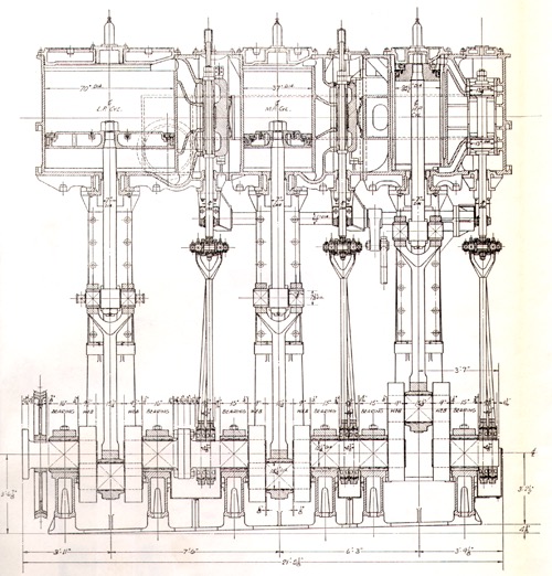
Main engine bedplate sketch The bedplate must be strong enough to withstand the weight of the engine and flexible enough to bend when the hull bends during the hogging and sagging of the vessel. Usually made of cast steel, a bedplate is manufactured by joining two longitudinal girders through multiple transverse girders.
On these transverse girders are semicircular cavities to support the crankshaft. Bedplate function:
Support the engine weight Support the dynamic load of the running parts Collect lube oil and drain it to the sump Hold the crankshaft in alignment at all times
A Frame As the name suggests, the A frame looks like the letter ‘A’. On the bottom, it rests on the bedplate and on the top, it supports the cylinder block (or entablature).
An A frame is erected over each transverse girder of the bedplate. A jointing compound is added between the A frame and the bedplate to improve sealing. The A frame secures itself to the engine through fitted bolts and tie bolts. Fitted bolts connect the bedplate and the A frame whereas the tiebolt secures the entablature, A frame and the bedplate with the vessel.
Main Engine A frame The A frame and the bedplate cavity (between transverse girders) form an enclosed space and isolate each unit of the engine. This enclosed space forms the crankcase for the engine. The entire A frame is cast as a single unit in the case of smaller engines. For larger engines, the complete A frame is cast as 2 or 3 separate units and then bolted together.
On the inside, the A frame houses the crosshead and the crosshead guide. The guides are machined in place in newer engines and cannot be adjusted. A frame function:
Hold the crankshaft in alignment House the crosshead and its guide Support the cylinder block or entablature Form the crankcase space
Entablature or cylinder block The entablature rests on top of the A frame and houses various parts of the engine such as the scavenge space, stuffingboxes, jacket cooling water spaces and the cylindrical cavity for the cylinder liner.
In older engines, the jacket cooling water space would be inside the entablature, but in newer engines the space is between the jacket and the liner and the jacket fits into the entablature. Main engine entablature in view from the ER middle platform The entablature’s structure is made strong enough to resist the combustion forces. Cast iron works best for the entablature.
Even here, fitted bolts are used to connect it to the engine. It is worth noting that the fitted bolts are used only for the purposes of alignment and location of the various parts.
They are not equipped to handle the engine’s firing forces that try to separate the three parts (Bedplate, A frame and entablature). That is a job for tie bolts. Entablature or Cylinder block function:
House the scavenge spaces and the liner cavity. Support the liner, the cooling water jacket, the cylinder head, the inlet and exhaust valve and other connected components Crankshaft
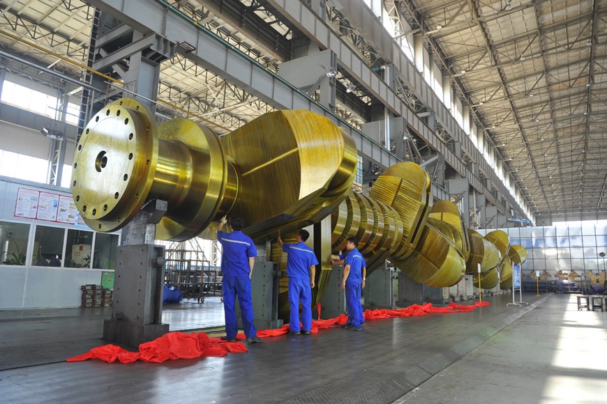
The crankshaft is one of the most critical components in the engine. This part along with the connecting rod is responsible for converting the reciprocating motion of the engine pistons into the rotational motion of the propeller. The propeller converts this torque into axial thrust and moves the vessel.
The crankshaft is subjected to a range of varying loads from the piston, combustion, propeller and the flywheel. It must therefore be designed keeping these cyclic loads in mind. Main engine crankshaft being assembled into the bedplate The crankshaft consist of the journal, crank webs and crank pin. It is generally made out of alloyed steel but the specific constituents used in the shaft vary on a case-to-case basis.
Elements such as silicon, nickel, vanadium, and chromium provide the characteristics for the crankshaft. To learn more about crankshafts, go to the following link: Types of Crankshaft. Crankshaft function:
Collect power from power generating units such as firing cylinders and transmit it to consumption units such the propeller, shaft generator, flywheel and the units in suction stroke Convert linear motion to rotational motion Distribute the axial and rotational forces generated during ship’s movement to the ship’s hull through axial and rotational bearings
Connecting rod The connecting rod (or con rod) connects to the crankshaft on one end and the crosshead on the other. As the piston moves up and down, it moves the crosshead with it, which in turn, imparts the same motion to the connecting rod.
Using this motion, the connecting rod moves the crank pin (and therefore the crankshaft) in a circular motion. The rod undergoes tensile, compressive, bending and buckling forces during the operation.
Exploded view of main engine connecting rod and crosshead assembly The piston side is known as the small end and the crank pin side is known as the big end. The connecting rod has bearings on both ends for a smooth and damage-free operation.
The connecting rod, just like the crankshaft, is under constant cyclic loading. This makes it vulnerable to fatigue failure and the connecting rod design accounts for it to ensure durability. Connecting rod function: Convert reciprocating motion of crosshead into rotational motion of the crankshaft
Supply oil from the crosshead to the crankpin through bores for cooling and lubrication Crosshead The crosshead is a rectangular part that acts as the link between the piston and the connecting rod.
It has a circular pin at the center known as the crosshead journal or the crosshead pin. The eye of the connecting rod’s small end fits onto this pin. The crosshead bearing cap has a provision through which the piston rod connects to the crosshead journal through studs and bolts.
The lubrication oil for the crosshead pin bearing is supplied through a telescopic pipe. Through drilled bores, the oil travels further to the piston as well as the crank pin for lubrication. On either side, the crosshead has guide shoes. The sliding faces of the shoes are lined with white metaland they traverse on rails known as the crosshead guides.
Crosshead function: Eliminate the side load on the piston and the cylinder liner by transmitting it to the engine structure instead of the piston Supply lubricating oil to the crank pin bearing and the piston
Allow the free movement of connecting rod outside of the cylinder Piston The piston is a composite part that converts the gas forces into mechanical forces for the engine.
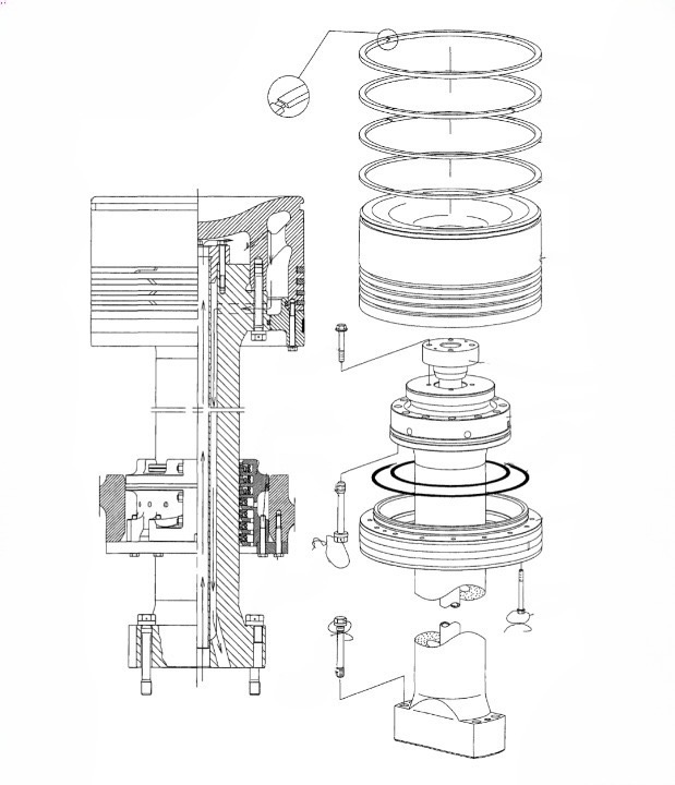
It fits into the engine cylinder and transmits the mechanical force to the piston rod (in the case of two stroke engines) or the connecting rod (in the case of four stroke engines). Main Engine piston and piston rod cross-section and exploded view
The two separate piston parts are the piston crown and the piston skirt. They are connected by 16 or more bolts on the underside of the skirt and then locked with locking wire. The piston rod is secured to the inside of the crown through another set of bolts.
The piston is subjected to high amounts of thermal and shock loading. They are usually heat treated Piston function: Deliver the power from the cylinder to the crankshaft through the crosshead and the connecting rod arrangement
Compress the air fuel mixture during the suction stroke Seal the combustion chamber and prevent the blowby of hot gases Cylinder liner
The cylinder liner fits inside the engine cylinder and acts as the combustion chamber for the engine. It is directly exposed to the compressed air-fuel mixture during the suction stroke and the combustion pressure during the power stroke.
Main engine cylinder liner and cooling jacket exploded view and cross-section The cylinder liner is a wearable part and a wear of 0.1 mm over 1000 hours is normal. If the wear exceeds this rate, further investigation is necessary to determine the cause and address it. Typically, a cylinder liner is replaced when the cylinder wear reaches 0.6-0.8% of the bore volume or as per the engine manufacturer’s guidelines.
Cylinder liner function: Carry out heat dissipation for the combustion process Form a sliding surface and facilitate the smooth movement of the piston
Ensure that the combustion chamber is air tight. The sealing capability reduces overtime as erosion occurs and the gap between the piston rings and the liner increases. Cylinder head or cylinder cover The cylinder head is the topmost part of the engine structure and houses various monitoring instruments and mountings such as the fuel valve (or fuel injector), starting air valve, cylinder relief valve, indicator valve, exhaust valve, etc.
It also has cavities for cooling water circulation. Main engine cylinder heads in view from the top platform
The cylinder head completes the sealing arrangement of the combustion chamber from the top. The space between the cylinder head and the cylinder liner is sealed using a mild steel ring also known as the sealing ring.
The cylinder head is also a part of the jacket cooling water system. It is provided with passages that receive water from the cylinder liner outlet. After cooling the cylinder head, the jacket water travels into the exhaust valve cooling spaces.
Cylinder head function: Seal the combustion chamber Transfer combustion forces to engine structure Act as a platform to deploy starting air and fuel into the system
Provide the passage of cooling water from the liner to the exhaust valve. Exhaust valve Each engine unit has its own exhaust valve that is mounted onto the central bore of its cylinder head.
Once the combustion is complete, the exhaust valve opens and extracts the exhaust gases from the combustion chamber. From the exhaust valves, the gases are first transferred to the manifold, then to heat recovery systems (turbocharger, economiser) and finally let out through the ship’s funnel.
Spare main engine exhaust valve A hydraulic oil pump controls the valve timing. The exhaust cam on the camshaft operates the hydraulic oil pump and opens the exhaust valve.
The hydraulic pressure can go up to 220 bars for opening the valve. Once the hydraulic pump’s roller comes off the cam profile, it relieves the pressure in the hydraulic line.
The spring air pushes the spring air piston upwards and closes the valve. The spring air pressure is about 7 bars. The exhaust gases are typically in the range of 350 to 400 degree Celsius and hence, cooling is provided through jacket water for heat dissipation.
Exhaust valve function: Extract the exhaust gases at the correct time for the set duration Maintain efficient sealing when closed to prevent compression air and exhaust gas leakage Transfer the gases to the manifold for further use
Camshaft The main engine camshaft is a rotating part with several fixed cams at varying angles. The camshaft derives power through the engine crankshaft through chains or gears. When it rotates, it rotates the cams with it.
The camshaft speed is the same as the crankshaft speed in a two-stroke engine and half of the crankshaft speed in a four-stroke engine. The number of camshafts in an engine depends on the type of engine. Inline engines have one camshaft, V-shaped engines have two.
The rollers on these cams have a single degree of freedom and can only go up or down. By virtue of this motion, the rollers operate various machinery. Camshaft function: Convert the rotational motion of crankshaft to the reciprocating motion of cam rollers
Operate inlet and exhaust valves in the case of four stroke engines and only exhaust valve in the case of two stroke engines Operate fuel injection pumps and the starting air distributor. However, common rail injection systems for fuel deployment are becoming common on modern vessels Turbocharger
The main engine turbocharger is a forced induction device that consists of a turbine and a compressor/blower. The two are arranged in a manner that enables the supply of pressurized fresh air to the combustion chamber.
The intention is to provide a greater amount of oxygen through air to increase the power output of the engine. Large marine engines typically have two turbochargers. The exhaust gases from each unit are collected in the exhaust manifold and supplied to the turbocharger turbine.
The moving particles in the exhaust gas move the turbine blade. The shaft of the turbine through appropriate sealing arrangements is connected to the impeller of a special compressor. Main engine sectioned turbocharger The compressor draws in atmospheric air and compresses it. This compression is responsible for the increase in power output.
As the mass of intake air increases, we can proportionately increase the fuel quantity and generate greater power compared to a similar-sized naturally aspirated engine. The process increases the temperature of the air to above 120 degrees C.
A charge air cooler reduces the temperature of the air to recommended levels and sends it to the scavenge manifold. Turbocharger function:
Increase the fresh air mass for combustion Utilize residual energy of exhaust gases for an improved engine efficiency Conclusion
While this is not an exhaustive list, we have tried to cover all the major parts of the marine diesel engine. All the parts in the engine must work in sync with each other for the engine to have stable parameters even when under varying loads.
An effective preventive maintenance system for all the engine parts is the key to the long and efficient operation of a marine engine. undefined


